Image to CAD
Drop a picture of a part — a PNG drawing, a JPG photo, a screenshot, a clean sketch — and get back a CAD file with true circle and arc entities you can measure, edit and cut. Powered by AI recognition rather than pixel tracing, checked against your original automatically, and free with no signup.
No watermark · no credit card · nothing you upload is stored · works in a phone browser, no app install
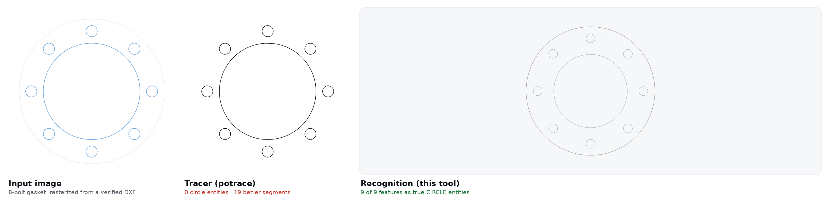
Tracing translates pixels. Recognition understands parts.
Ask an engineering forum about converting an image to CAD and the standing answer is “you'll have to trace it by hand” — because every free converter that ranks for these searches is a tracer: it finds pixel boundaries and emits bezier curves. That is the right tool for turning a logo into vector art and the wrong one for a part, because a traced hole is not a hole. It is a closed curve blob that CAM software cannot drill, offset or count.
We measured the difference instead of asserting it. Parts with known geometry were rasterized and converted both ways; ground truth is the DXF each image was made from.
| Test part | Real features | Tracer recovered | Recognition recovered |
|---|---|---|---|
| Gasket, 8-bolt | 9 pierces | 0 circles — 19 beziers | 9 of 9 |
| Plate with 40 mm bore | 5 pierces | 0 circles — 11 beziers | 5 of 5 |
| LED panel | 4 pierces | 0 circles — 9 beziers | 4 of 4 |
Run 4 August 2026, method and every number in the published benchmark. Counts were exact in all 18 cases across both PNG and JPG inputs; large-feature proportions held within a few percent; small hole diameters drifted more — which is why the output is measured on screen before you download, and auto-checked against your original.
PNG to CAD, and PNG to DXF
PNG is the strongest input. It is lossless, so an exported drawing view, a CAD screenshot or a cleaned scan keeps its edges exactly where the source put them — no compression halo around line work. In the measured runs, every PNG input came back with exact feature counts. Transparent backgrounds are flattened to white automatically, so alpha-channel exports convert without the black-background surprise; dark-mode screenshots usually read fine, but line-art convention is dark-on-light — invert first if a result looks wrong.
Best PNG candidates: exported drawing views, screenshots of drawings, cutting templates, laser-project outlines, scans cleaned to line art. A photograph saved as .png is still a photograph — the section below applies to it.
JPG to CAD, and JPG to DXF
JPG is the format of photographs and email attachments, and the standing fear is that compression artifacts destroy the geometry. We tested that: the same parts re-encoded at JPEG quality 70 — an aggressive setting — changed zero recognized feature counts. Artifact noise ruins pixel tracers, whose wobbling curves follow every speck; recognition reads “8 holes on a bolt circle” through the noise, the way you do.
How to photograph a drawing so it converts:
- Directly above, lens parallel to the paper. Perspective skew is the one error that survives conversion.
- One part filling the frame. Crop out the desk and the other details on the sheet.
- Even, matte light — a shadow across line work reads as an edge. No flash on glossy paper.
- Sharpness over megapixels. Anything above roughly 800 px on the long side is enough.
- Know one true dimension for the scale question.
Picture, photo or sketch to CAD
| Picture | Converts? | Note |
|---|---|---|
| Screenshot or export of a drawing | Best case | Lossless line art — exact counts in our runs |
| Flat-on photo of a drawing | Yes | Follow the shooting steps above |
| Clean pencil sketch | Yes, with care | Firm outline and visible proportions; the scale answer does the rest |
| Flat part photographed straight down | Often | Gaskets, plates, brackets on a plain background |
| Angled photo, cluttered scene | Poorly | Skew transfers into the geometry — reshoot flat-on |
| Photo of a complex 3D object | Refused | A profile needs a flat view; the tool says so instead of guessing |
Logos and artwork for CNC or laser cutting
The most common forum version of this task is a logo that needs to become cuttable linework. Honest guidance: if the logo is geometric — shapes, letters as outlines, a badge with holes — recognition returns clean entities you can cut. If it is detailed artwork with gradients and fine curves, a dedicated art vectorizer will follow those curves more faithfully than a parts-oriented recognizer, and you should use one, then expect polylines rather than circles. The dividing question is the same as everywhere on this page: do you need art reproduced, or geometry you can measure?
Want a CAD-style drawing image instead?
Several tools ranking for “image to CAD” are AI image generators: they output a JPG or PNG styled like a blueprint — often attractive, never openable in CAD. If that is what you want (an illustration, a poster, concept art), those tools serve it and this one does not. If you need a file AutoCAD can open and a laser can cut, a picture of a drawing is exactly what you already have — the thing you need is the DXF. The comparison page sorts the market by which side of that line each tool is on.
What comes out, precisely
- R12 ASCII DXF at 1:1 — the revision every laser cutter, CNC controller and CAM package imports without complaint. SVG alongside it.
- True entity types: holes as
CIRCLE, curves asARC, outlines as polylines/rects — the entity summary is printed under every result, and the measured panel lists size and every hole diameter. - Units and scale: millimetres, calibrated by your one reference dimension (inches accepted and converted).
- Layers: profile and cuts separated, documented here.
- Opens in: AutoCAD, Fusion, SolidWorks, FreeCAD, LibreCAD, QCAD — no plugin. DWG is one SAVEAS away when a workflow demands it.
- Then it checks itself: the recognized geometry is rendered and compared against your original image, corrections are applied automatically, and the verdict is printed next to the download. You can stop it or download at any point.
Where it fails, stated plainly
- Perspective skews geometry. Shoot flat-on; the converter cannot un-skew what it cannot see.
- Small holes drift. Counts were exact in our runs; a 6 mm hole read from an 800-pixel image can still come back 20% off. The measured panel exists so you catch it before cutting — correct critical diameters in CAD, or state the part in text mode where dimensions are exact by construction.
- One part per image. Multi-view sheets confuse recognition; crop.
- Organic shapes are refused, not approximated — parametric CAD is the wrong tool for them and the tool says so.
- Drawing sheets in PDF have their own page: PDF to CAD, including the vector-versus-scan difference.
Questions
Can I convert an image to CAD for free?
Yes. AI CAD Generator converts PNG, JPG and WebP images to DXF free, with no signup, no watermark and no credit card. The output is measured on screen — size, hole count, hole diameters — before you download it, and it works in a phone browser with nothing to install.
How is AI recognition different from the tracing other converters use?
A tracer converts pixel boundaries into bezier curves: in our published test, potrace returned 0 circle entities on parts containing 18 round features. Recognition reads what the part is and rebuilds it as true CIRCLE and ARC entities — 18 of 18 features counted correctly on the same images — so holes stay drillable, countable and editable in CAD.
How does the converter know the real size of the part?
No image carries absolute scale, so it does not guess: it recovers shape and proportions, then asks for one real dimension — or reads a legible dimension printed on the drawing and asks you to confirm it. Everything scales deterministically from that answer.
Which converts better, PNG or JPG?
PNG is the cleanest input because it is lossless — exported drawings and screenshots keep razor edges. But JPG holds up better than assumed: quality-70 JPEG compression changed zero recognized feature counts in our measured test. Shoot photos flat-on and either format works.
Can it turn a photo or hand-drawn sketch into a CAD drawing?
A flat-on photo of a drawing, a clean pencil sketch with firm lines, or a flat part photographed straight down all convert. Perspective shots, cluttered scenes and photos of complex 3D objects do not — the tool refuses and says why instead of returning decorative geometry.
Does the DXF open in AutoCAD, and can I get a DWG?
Yes. Output is R12 ASCII DXF — the revision with the widest support — and AutoCAD, Fusion, SolidWorks, FreeCAD and LibreCAD open it directly. If a workflow requires DWG, open the DXF in AutoCAD and SAVEAS: one step, nothing lost.
Does it convert floor plans or full drawing sheets?
One part per image converts best. Simple floor-plan outlines can work, but dense sheets with dimension strings, hatching and multiple views recognize poorly — crop to the geometry you need, and expect the tool to state medium or low confidence when a read is uncertain.
Is anything I upload stored?
No. Images are processed for the conversion and not saved by this site — there is no account system and no gallery of user uploads. The privacy page spells out exactly what is and is not retained.
Or describe it instead
When you can say “plate 120 × 80 mm, four 6 mm holes inset 10 mm”, the free AI CAD generator builds it from text with every stated dimension exact — and iterates against its own measurements until they match.
Open the full tool