26 parts, each generated from a single line of text by this ai cad generator, then re-parsed with an independent DXF library and measured. A part only appears here if its measured geometry matched the dimensions the prompt stated.
Every file is R12 ASCII DXF at 1:1 in millimetres, public domain, free for commercial use. They are nominal profiles: apply your own kerf compensation and lead-ins in CAM, and see what each layer means before cutting.
Mounting plates
Flat plates with bolt patterns and bores.
120 × 80 mmDXF
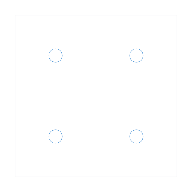
Mounting plate 120 x 80 mm with four 6 mm holes, one inset 10 mm from each corner4 holes: 4 × ⌀6 · layers CUTS, PROFILEDownload the DXF
200 × 100 mmDXF
Mounting plate 200 x 100 mm with six 8 mm holes in two rows of three, inset 15 mm6 holes: 6 × ⌀8 · layers CUTS, PROFILEDownload the DXF
150 × 100 mmDXF
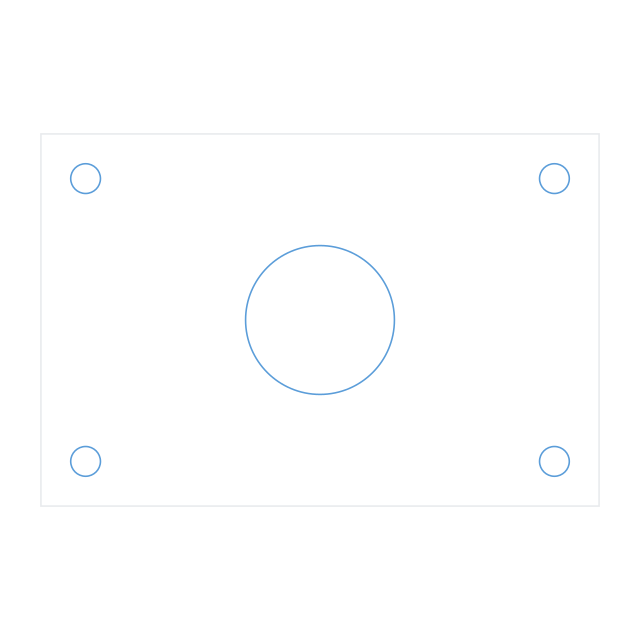
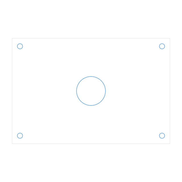
Plate 150 x 100 mm with one 40 mm centre bore and four 8 mm holes, one inset 12 mm from each corner5 holes: 4 × ⌀8, 1 × ⌀40 · layers CUTS, PROFILEDownload the DXF
100 × 100 mmDXF
Plate 100 x 100 mm with 12 mm radius rounded corners and one 30 mm hole in the centre1 hole: 1 × ⌀30 · layers CUTS, PROFILEDownload the DXF
80 × 60 mmDXF
Electronics mounting plate 80 x 60 mm with four 3.4 mm holes, one inset 5 mm from each corner4 holes: 4 × ⌀3.4 · layers CUTS, PROFILEDownload the DXF
Flanges
Flange faces dimensioned to ASME B16.5 and EN 1092-1.
190.5 × 190.5 mmDXF
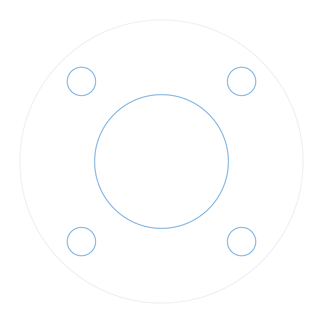
ASME B16.5 class 150 three inch flange face: 190.5 mm outer diameter, one 90 mm centre bore, four 19.1 mm bolt holes on a 152.4 mm bolt circle5 holes: 4 × ⌀19.1, 1 × ⌀90 · layers CUTS, PROFILEDownload the DXF
228.6 × 228.6 mmDXF
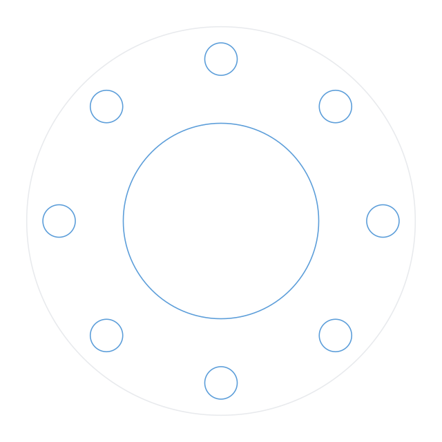
ASME B16.5 class 150 four inch flange face: 228.6 mm outer diameter, one 115 mm centre bore, eight 19.1 mm bolt holes on a 190.5 mm bolt circle9 holes: 8 × ⌀19.1, 1 × ⌀115 · layers CUTS, PROFILEDownload the DXF
165 × 165 mmDXF
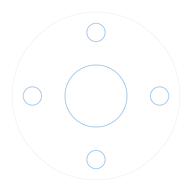
EN 1092-1 DN50 PN16 flange: 165 mm outer diameter, one 61 mm centre bore, four 18 mm bolt holes on a 125 mm bolt circle5 holes: 4 × ⌀18, 1 × ⌀61 · layers CUTS, PROFILEDownload the DXF
Gaskets
Sealing profiles with matched bolt patterns.
120 × 120 mmDXF
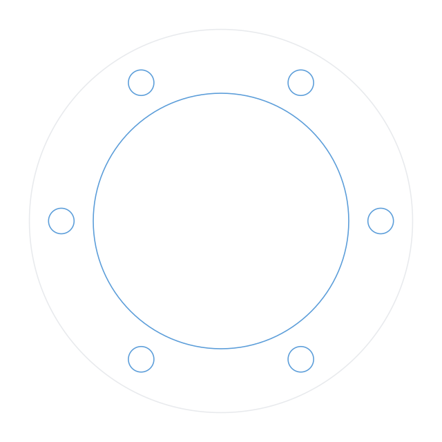
Gasket 120 mm outer diameter, one 80 mm inner diameter opening, six 8 mm bolt holes on a 100 mm bolt circle7 holes: 6 × ⌀8, 1 × ⌀80 · layers CUTS, PROFILEDownload the DXF
90 × 90 mmDXF
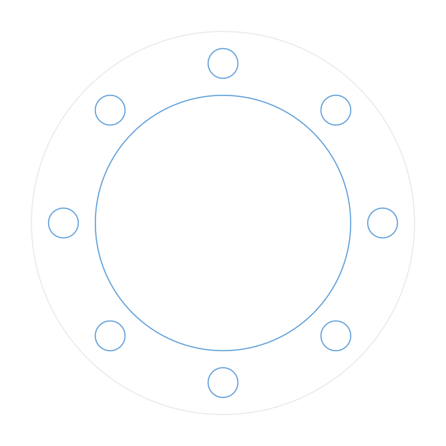
Gasket 90 mm outer diameter, one 60 mm inner diameter opening, eight 7 mm bolt holes on a 75 mm bolt circle9 holes: 8 × ⌀7, 1 × ⌀60 · layers CUTS, PROFILEDownload the DXF
100 × 100 mmDXF
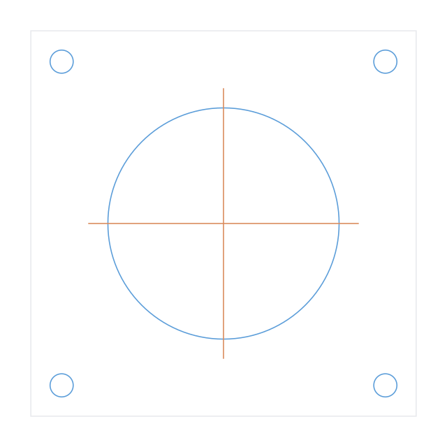
Square gasket 100 x 100 mm with one 60 mm circular opening and four 6 mm holes, one inset 8 mm from each corner5 holes: 4 × ⌀6, 1 × ⌀60 · layers CUTS, PROFILEDownload the DXF
Enclosure panels
Face and rear panels with switch, LED and connector cutouts.
120 × 80 mmDXF
Enclosure face panel 120 x 80 mm with one 22 mm switch hole and four 4 mm holes, one inset 6 mm from each corner5 holes: 4 × ⌀4, 1 × ⌀22Download the DXF
150 × 60 mmDXF
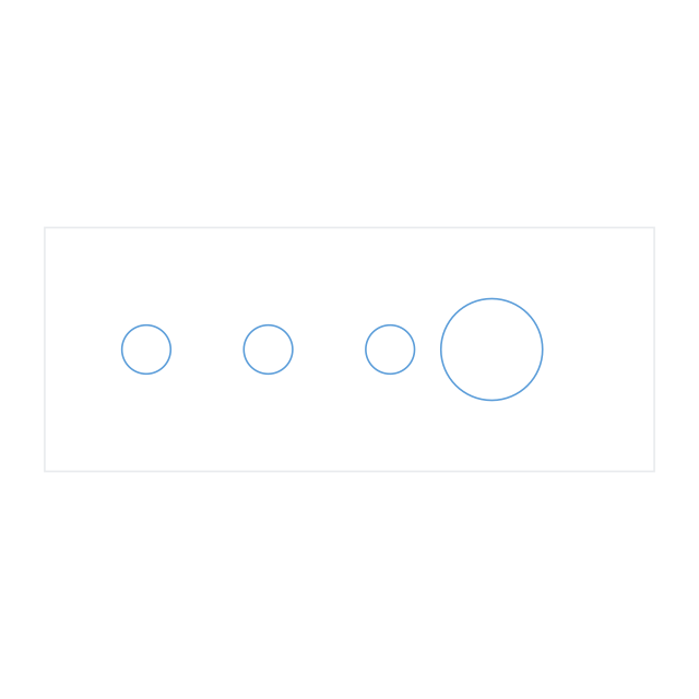
Front panel 150 x 60 mm with three 12 mm LED holes spaced 30 mm apart and one 25 mm dial hole4 holes: 3 × ⌀12, 1 × ⌀25 · layers CUTS, PROFILEDownload the DXF
100 × 50 mmDXF
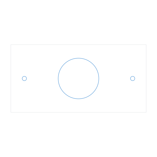
Rear panel 100 x 50 mm with one 30 mm round connector cutout and two 3.2 mm mounting holes3 holes: 2 × ⌀3.2, 1 × ⌀30 · layers CUTS, PROFILEDownload the DXF
100 × 60 mmDXF
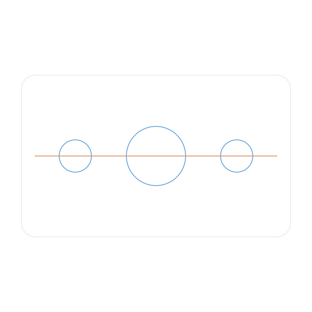
Face plate 100 x 60 mm with 5 mm radius rounded corners, one 22 mm switch hole and two 12 mm holes3 holes: 2 × ⌀12, 1 × ⌀22 · layers CUTS, PROFILEDownload the DXF
200 × 90 mmDXF
Instrument panel 200 x 90 mm with two 22 mm switch holes 60 mm apart and four 8 mm LED holes6 holes: 4 × ⌀8, 2 × ⌀22 · layers CUTS, PROFILEDownload the DXF
Bracket profiles
Outlines with bend lines and slots marked on separate layers. Bend allowance is not applied.
80 × 40 mmDXF
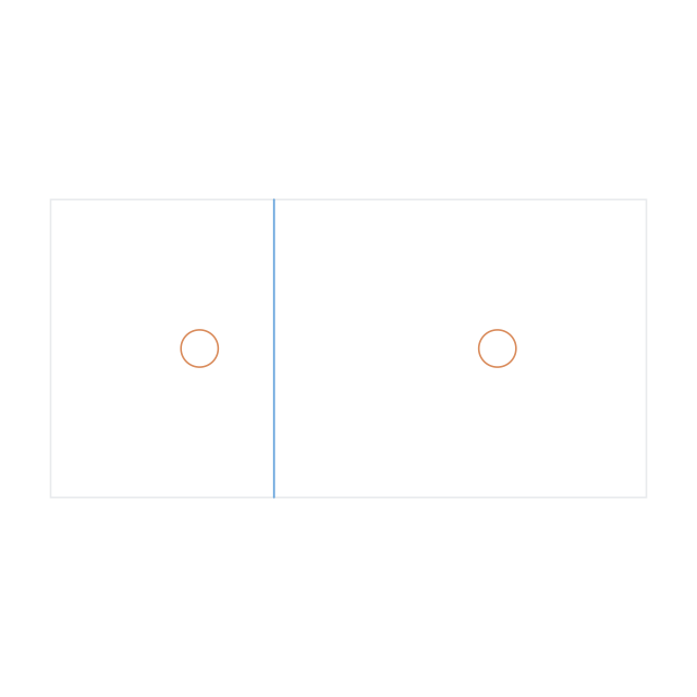
Profile for an L-bracket, 80 x 40 mm outline, bend line at 30 mm on its own layer, four 5 mm holes: two on each side of the bend4 holes: 4 × ⌀5 · layers BEND, CUTS, PROFILEDownload the DXF
60 × 60 mmDXF
Corner bracket profile 60 x 60 mm with a bend line at 30 mm and four 5 mm holes4 holes: 4 × ⌀5 · layers BEND, CUTS, PROFILEDownload the DXF
100 × 40 mmDXF
Adjustment plate 100 x 40 mm with two slots, each 8 mm wide and 30 mm long overall, running lengthwise9 entities, no round features · layers CUTS, PROFILEDownload the DXF
80 × 30 mmDXF
Plate 80 x 30 mm with one horizontal slot 6 mm wide and 40 mm long overall, centred5 entities, no round features · layers CUTS, PROFILEDownload the DXF
Rings and washers
Shims, spacers and thrust washers.
50 × 50 mmDXF
Shim ring 50 mm outer diameter with one 30 mm inner diameter opening1 hole: 1 × ⌀30 · layers CUTS, PROFILEDownload the DXF
25 × 25 mmDXF
Spacer washer 25 mm outer diameter with one 10.5 mm inner diameter opening1 hole: 1 × ⌀10.5 · layers CUTS, PROFILEDownload the DXF
80 × 80 mmDXF
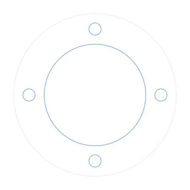
Thrust washer 80 mm outer diameter, one 50 mm inner diameter opening, four 6 mm holes on a 65 mm bolt circle5 holes: 4 × ⌀6, 1 × ⌀50 · layers CUTS, PROFILEDownload the DXF
Discs
Index plates, pulley blanks and wheel blanks.
120 × 120 mmDXF
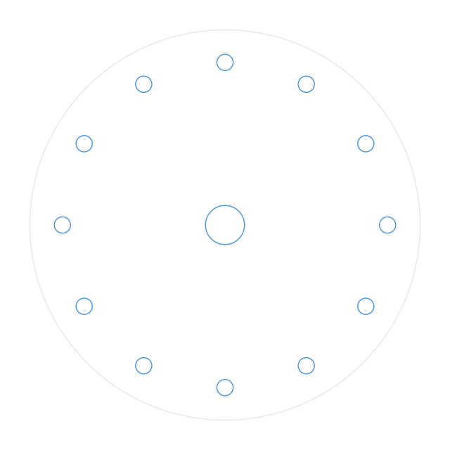
Index disc 120 mm diameter with twelve 5 mm holes on a 100 mm bolt circle and one 12 mm centre bore13 holes: 12 × ⌀5, 1 × ⌀12 · layers CUTS, PROFILEDownload the DXF
90 × 90 mmDXF
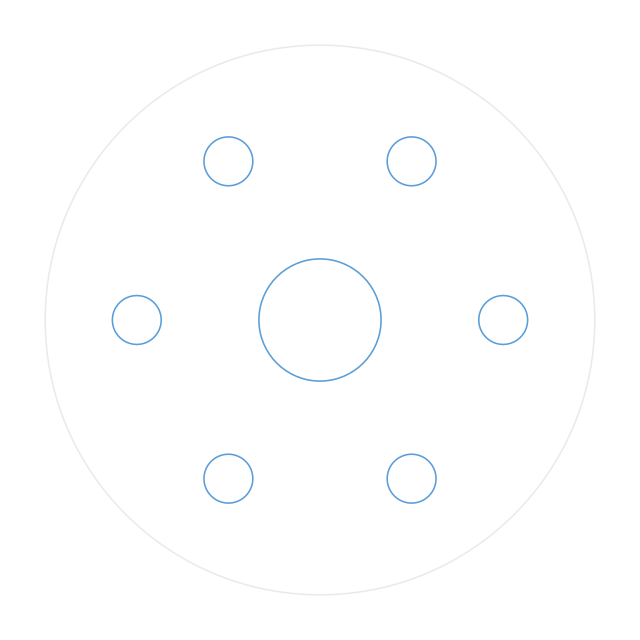
Pulley blank 90 mm diameter with one 20 mm centre bore and six 8 mm lightening holes on a 60 mm bolt circle7 holes: 6 × ⌀8, 1 × ⌀20 · layers CUTS, PROFILEDownload the DXF
150 × 150 mmDXF
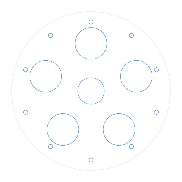
Wheel blank 150 mm diameter with one 25 mm centre bore, five 30 mm lightening holes on a 90 mm bolt circle, and ten 4 mm holes on a 130 mm bolt circle16 holes: 10 × ⌀4, 1 × ⌀25, 5 × ⌀30 · layers CUTS, PROFILEDownload the DXF
Need one that is not here?
Describe it and the AI CAD drawing generator will build it. No account, no credits, a generous hourly rate limit.