AI image to CAD, measured
Claims about AI image to CAD conversion are cheap, so here is a measurement instead. We took parts whose geometry we know exactly, turned them into images, converted those images two ways — the tracing approach every free converter site uses, and the recognition approach behind this site's image to CAD tool — and scored both against the original files.
The result in one figure
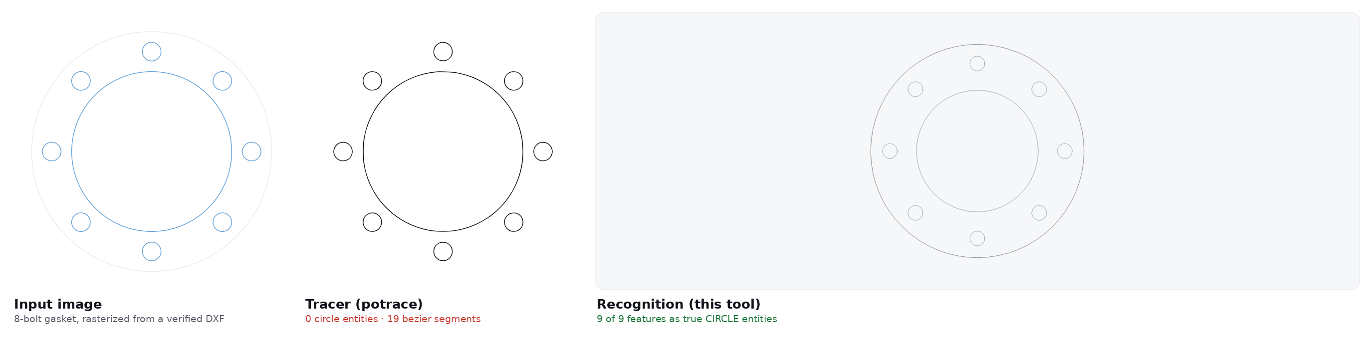
Method
- Ground truth: three parts from the verified library — an 8-bolt gasket (9 pierces), a plate with a 40 mm bore (5 pierces), an LED panel (4 pierces). Each exists as a DXF whose every dimension was independently re-measured when the library was built.
- Inputs: each part's drawing rasterized to an 800-pixel PNG, and the same PNG re-encoded as a quality-70 JPEG to test compression damage. Six images total.
- Tracer condition: potrace 1.16 at threshold 200 — the engine class behind most “free image to DXF” converters. We count what its output contains.
- Recognition condition: the exact production prompt this site runs — the benchmark script extracts it from the deployed route's source so the test cannot quietly drift from the product.
- Scoring: feature counts against ground truth; proportion ratios (bore-to-width, outer-to-inner) against the known values. Costs recorded: the full recognition side of this run cost $0.08.
Counts: 18 of 18 vs 0
| Part | Format | True pierces | Tracer circles | Recognition |
|---|---|---|---|---|
| Gasket, 8-bolt | PNG | 9 | 0 (19 beziers) | 9 · high conf. |
| JPG q70 | 9 | 0 (19 beziers) | 9 · high conf. | |
| Plate with bore | PNG | 5 | 0 (11 beziers) | 5 · high conf. |
| JPG q70 | 5 | 0 (11 beziers) | 5 · high conf. | |
| LED panel | PNG | 4 | 0 (9 beziers) | 4 · medium conf. |
| JPG q70 | 4 | 0 (9 beziers) | 4 · high conf. |
The tracer number deserves a precise reading: potrace did not fail. It did exactly what tracing is — it converted pixel boundaries into curves, faithfully. The problem is that a curve that looks like a circle is not a circle: CAM software cannot drill it, offset it, or count it, and a CAD user cannot change its diameter. Tracing is the right tool for logos. Parts need entities.
Proportions: where recognition is strong and where it drifts
- Large features held within a few percent. The 40 mm bore on the 150 mm plate came back 2.6% off true proportion from PNG, 1.2% from JPG. The 25 mm dial on the panel: 3% and 1% respectively.
- The gasket's inner opening read ~15% small (ratio 1.75 vs a true 1.5) in both formats — the one systematic proportion miss in this run, disclosed rather than averaged away.
- Small holes drift most. The plate's 8 mm holes came back 30% under from the clean PNG and 2% over from the JPG — noise, not a format effect. Counts never moved.
- Compression was a non-event. Quality-70 JPEG changed zero counts. Recognition reads the part through artifact noise; it is pixel-level tracers that artifacts hurt.
This drift is why the tool's output panel shows measured dimensions computed from the generated geometry — the same philosophy as the text-track accuracy page: measurement over assertion, and the user sees what came out before anything gets cut.
What this does not show
- n is 3 parts × 2 formats. It is a controlled comparison, not a survey; the input images are clean renders, not wrinkled photocopies.
- Absolute scale is out of scope by design: no image carries millimetres. The production flow asks one dimension and scales deterministically — how that works.
- Freeform shapes were not tested; parametric recognition is the wrong tool for them and the generator says so at runtime.
Run the same test yourself
Take any file from the library, screenshot it, and feed the screenshot to the image to CAD converter. Compare the measured panel to the original's stated dimensions — that is the entire benchmark, minus the script.
Try the converter